We use cookies to make your experience better. To comply with the new e-Privacy directive, we need to ask for your consent to set the cookies. Learn more
Danfoss CS Air Compressor Switches
Danfoss CS range of air compressor pressure switches offer superior pressure regulation for air compressors. Danfoss produce air compressor pressure switches with or without a relief unloader valve to sense line pressure and provide a control signal to system valves.
Pressure switch type CS is part of the Danfoss pressure control range. All CS pressure switches have a built-in pressure-operated, three-pole or one-pole switch, the contact position of which depends on
− the pressure in the connector
− the range setting.
The pressure switches are fitted with a manual switch that will lock the contact system in the open position independently of the pressure in the system.
CS product range
• Standard CS pressure switches
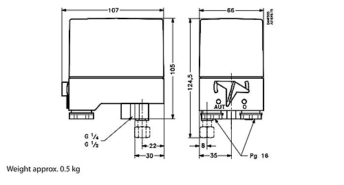
− pressure connection: G ½ or G ¼
• CS pressure switches with special pressure connection made of polyacetal
− suitable in drinking water applications
− pressure connection: G ½
Stop pressure range Pressure switches are supplied in the following three versions:
− low-pressure, 2-6 bar
− intermediate pressure, 4-12 bar
− high-pressure, 7-20 bar.
Contact system
Three-pole (TPST), contact system which opens on rising pressure. The contact system is touch-safe with open terminals, self-lifting terminal screws and star/slot screws.
Cable entry
The pressure switches have threads for two PG 16 screwed cable entries.
Screwed cable entries
Screwed cable entries are supplied with single pack CS pressure switches. Screwed cable entries for CS in industrial packs must be ordered separately under code no. 031E029366 containing seals and Pg 16 nuts.
Pressure relief valve
This valve relieves (unloader valves) pressure on the compressor piston. It can be supplied as an accessory and must be ordered separately. The valve has an M10 x 1 external thread, union nut and cutting ring. The nut and cutting ring are both available in 6 mm and 1/4 inch sizes.
Manual switch
When the manual switch has been used to lock the contact system in its open position, the cover can be removed without the plant starting.
Enclosure
The enclosure is made of plastic (PA 6) and is obtainable in IP 43 or IP 55 versions to IEC 529. A knockout in the base of the enclosure can be removed to provide a drain hole for condensate.
|
Code number |
Type |
Regul. range [bar] Pe |
Conn. size |
Diff. min. range setting [bar] |
Diff. max. range setting [bar] |
Max. working pressure [bar] Pe |
Contact function |
Encl. |
|
031E020066 |
CS |
2,00 - 6,00 bar |
G 1/4 |
0,72 - 1,00 bar |
1,00 - 2,00 bar |
6,0 bar |
TPST |
IP43 |
|
031E020266 |
CS |
2,00 - 6,00 bar |
G 1/4 |
0,72 - 1,00 bar |
1,00 - 2,00 bar |
6,0 bar |
SPDT |
IP43 |
|
031E020566 |
CS |
2,00 - 6,00 bar |
G 1/4 |
0,72 - 1,00 bar |
1,00 - 2,00 bar |
6,0 bar |
TPST |
IP55 |
|
031E021066 |
CS |
2,00 - 6,00 bar |
G 1/2 A |
0,72 - 1,00 bar |
1,00 - 2,00 bar |
6,0 bar |
TPST |
IP43 |
|
031E021566 |
CS |
2,00 - 6,00 bar |
G 1/2 A |
0,72 - 1,00 bar |
1,00 - 2,00 bar |
6,0 bar |
TPST |
IP55 |
|
031E021866 |
CS |
2,00 - 6,00 bar |
G 1/2 A |
0,72 - 1,00 bar |
1,00 - 2,00 bar |
6,0 bar |
TPST |
IP55 |
|
031E022066 |
CS |
4,00 - 12,00 bar |
G 1/4 |
1,00 - 1,50 bar |
2,00 - 4,00 bar |
12,0 bar |
TPST |
IP43 |
|
031E022566 |
CS |
4,00 - 12,00 bar |
G 1/4 |
1,00 - 1,50 bar |
2,00 - 4,00 bar |
12,0 bar |
TPST |
IP55 |
|
031E023066 |
CS |
4,00 - 12,00 bar |
G 1/2 A |
1,00 - 1,50 bar |
2,00 - 4,00 bar |
12,0 bar |
TPST |
IP43 |
|
031E023566 |
CS |
4,00 - 12,00 bar |
G 1/2 A |
1,00 - 1,50 bar |
2,00 - 4,00 bar |
12,0 bar |
TPST |
IP55 |
|
031E024066 |
CS |
7,00 - 20,00 bar |
G 1/4 |
2,00 - 3,50 bar |
3,50 - 7,00 bar |
20,0 bar |
TPST |
IP43 |
|
031E024566 |
CS |
7,00 - 20,00 bar |
G 1/4 |
2,00 - 3,50 bar |
3,50 - 7,00 bar |
20,0 bar |
TPST |
IP55 |
|
031E025066 |
CS |
7,00 - 20,00 bar |
G 1/2 A |
2,00 - 3,50 bar |
3,50 - 7,00 bar |
20,0 bar |
TPST |
IP43 |
|
031E025566 |
CS |
7,00 - 20,00 bar |
G 1/2 A |
2,00 - 3,50 bar |
3,50 - 7,00 bar |
20,0 bar |
TPST |
IP55 |
|
031E026566 |
CS |
2,00 - 6,00 bar |
G 1/2 A |
0,72 - 1,00 bar |
1,00 - 2,00 bar |
6,0 bar |
TPST |
IP55 |
|
031E027166 |
CS |
4,00 - 12,00 bar |
G 1/2 A |
1,00 - 1,50 bar |
2,00 - 4,00 bar |
12,0 bar |
TPST |
IP43 |
|
031E101066 |
CS |
2,00 - 6,00 bar |
G 1/2 A |
0,72 - 1,00 bar |
1,00 - 2,00 bar |
6,0 bar |
TPST |
IP43 |
|
031E101266 |
CS |
4,00 - 12,00 bar |
G 1/2 A |
1,00 - 1,50 bar |
2,00 - 4,00 bar |
12,0 bar |
TPST |
IP43 |
|
031E101466 |
CS |
7,00 - 20,00 bar |
G 1/2 A |
2,00 - 3,50 bar |
3,50 - 7,00 bar |
20,0 bar |
TPST |
IP43 |
|
031E218866 |
CS |
2,00 - 6,00 bar |
G 1/2 A |
0,72 - 1,00 bar |
1,00 - 2,00 bar |
6,0 bar |
TPST |
IP43 |
|
031E219166 |
CS |
2,00 - 6,00 bar |
G 1/2 A |
0,72 - 1,00 bar |
1,00 - 2,00 bar |
6,0 bar |
TPST |
IP43 |
Pressure switches types PS and PSU
** OBSOLETE replaced by CS range- Table for pressure reference only ***
Types PS and PSU were pressure controlled three-pole switches. The position of the contacts depended on the pressure in the inlet connection and the range setting.
Pressure switch type PS was for the automatic stop and start of motors in compressed air and water pressure plant (pressure storage tanks).
Type PSU were especially for compressed air plant where pressure over the compressor piston must be relieved before re starting.
|
Code number |
Type |
Regul. range [bar] Pe |
Conn. size |
Diff. min. range setting [bar] |
Diff. max. range setting [bar] |
Max. working pressure [bar] Pe |
With unloader valve |
Without unloader valve |
|
031E0171 |
PS4B |
1 – 4 bar |
G 1/2 A |
0.6 – 0.7 bar |
3 |
20 bar |
|
X |
|
031E0172 |
PSU4B |
1 – 4 bar |
G 1/2 A |
0.6 – 0.7 bar |
3 |
20 bar |
X |
|
|
031E0182 |
PS7B |
1 – 7 bar |
G 1/2 A |
0.95 – 1.3 bar |
3 |
20 bar |
|
X |
|
031E0175 |
PS9B |
2.5 – 9.5 bar |
G 1/2 A |
1.2 – 1.8 bar |
7 |
25 bar |
|
X |
|
031E0176 |
PSU9B |
2.5 – 9.5 bar |
G 1/2 A |
1.2 – 1.8 bar |
7 |
25 bar |
X |
|
|
031E0179 |
PS15B |
7 – 15 bar |
G 1/2 A |
1.7 – 2.3 bar |
7 |
25 bar |
|
X |
|
031E0180 |
PSU15B |
7 – 15 bar |
G 1/2 A |
1.7 – 2.3 bar |
7 |
25 bap |
X |
|
Conversion table PS/PSU to CS Switches
|
Old Version |
New Version |
||||||
|
Type |
Code No. |
Relief Valve Included |
Stop Pressure Range BAR |
Stop Pressure Range BAR |
Code No. |
Type |
Order Relief Valve Separately |
|
PS 4B |
031E0171 |
No |
1 to 4 |
2 to 6 |
031E021566 |
CS |
No |
|
PSU 4B |
031E0172 |
Yes |
1 to 4 |
2 to 6 |
031E021566 |
CS |
031E029866 |
|
PS 7B |
031E0183 |
No |
1 to 7 |
2 to 6 4 to 12 |
031E021566 031E023566 |
CS |
No |
|
PS 9B |
031E0175 |
No |
2.5 to 9.5 |
2 to 6 4 to 12 |
031E021566 031E023566 |
CS |
No |
|
PSU 9B |
031E0176 |
Yes |
2.5 to 9.5 |
2 to 6 4 to 12 |
031E025566 031E023566 |
CS |
031E029866 |
|
PS 15B |
031E0179 |
No |
7 to 15 |
7 to 20 |
031E025566 |
CS |
No |
|
PSU 15B |
031E0180 |
Yes |
7 to 15 |
7 to 20 |
031E025566 |
CS |
031E029866 |
|
PSU 20 |
031E0191 |
Yes |
7 to 20 |
7 to 20 |
031E025566 |
CS |
031E029866 |
|
When the old pressure range is not covered by one new product completely, please select new switch based on set pressure point. |
Pressure switches types PS and PSU - Obsolete
Types PS and PSU were pressure controlled three-pole switches. The position of the contacts depended on the pressure in the inlet connection and the range setting.
Pressure switch type PS was for the automatic stop and start of motors in compressed air and water pressure plant (pressure storage tanks).
Type PSU were especially for compressed air plant where pressure over the compressor piston must be relieved before re starting.
PS-PSU Specifications
Switch
Three-pole switch (TPST) that breaks on rising pressure.
Connections
Process connection: 1/2" bsp female
Pressure relief valve: 1/4" flare connection
Contact load
Alternating current: 9 A (AC,) at Ue = 500 V
Motor load : 4 kW (5.5 hp) at
3 x 380/415 V
1.1 kW (1.5 hp) at
1 x 220/240 V
Direct current : 6 A, 220 V
Vibration-resistance
Vibration-stable in the range 10•200 Hz, 2 g
Enclosure
IP 55 to IEC 529
The base is made of grey-enamelled steel plate, the top of grey polypropylene. The cover is fastened with two stainless steel screws. All pressure switches have a manual switch fitted on the side of the base.
Mechanical life: 400000 operations
Cable entry
Two Pg 16 screwed cable entries for cable diameters from 9 to 15 mm.
Materials in contact with the medium
Membrane: Nitrile rubber
Pressure connector: Silumin
Electrical life : 100000 operations
Identification
The type designation and code number are stamped in the side of the unit.
Ambient temperature: -20 to + 70°C
Temperature of medium : - 20 to + 100°c
Spare parts
Contact set: code no. 031E0065 (no longer available)
Diaphragm: code no. 031E0346 (no longer available)
Flange: code no. 031E0400 (no longer available)
Click to purchase CS Pressure Switches